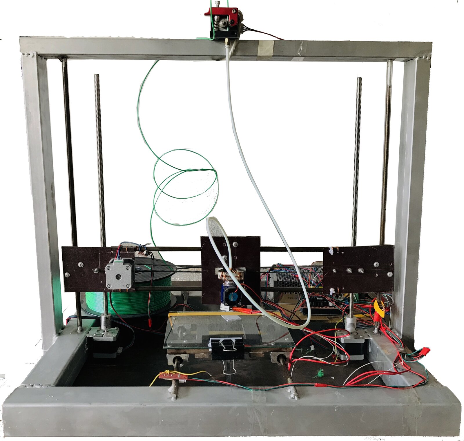
Project Overview
A CNC 3D printer designed and built by our five-member group (Group C-17) for the course ME 366: Electro-Mechanical System Design and Practice at BUET. Building a printer from tutorials looks easy, but making it print accurately takes a great deal of calibration, so our goal was not only to build the printer but to document how we calibrated it. Most 3D printers used in Bangladesh are imported; we hoped the design could help local makers build their own.
Design and Hardware
- Design: Modelled in SolidWorks.
- Frame: 50 mm × 50 mm × 5 mm mild steel square channel, chosen for its low cost, local availability and weldability.
- Motion: NEMA 17 stepper motors on the X, Y and Z axes, with GT2 pulleys and timing belts for X and Y, and an M8 threaded rod for Z. Mechanical endstops limit the travel on each axis.
- Print bed: Fiber board, 19 cm × 15 cm.
- Extrusion: MK8 extruder feeding PLA filament to an E3D V6 hotend.
- Electronics: Arduino Mega 2560 with a RAMPS 1.4 shield, A4988 stepper drivers (1/16 microstepping) and a 12 V, 20 A power supply.
Programming and Calibration
- Firmware: Marlin, configured for our endstops, temperature sensor, print bed size and steps/mm on each axis.
- Workflow: SolidWorks model → STL → G-code in Slic3r → printed through Pronterface.
- Calibration: Stepper steps/mm for each axis and the extruder, the A4988 driver current (VREF = 0.72 V for a 1.8 A current limit), endstop positions and a steady PLA feed.
Documentation
Our full build and calibration documentation is on the project website here.